Overview
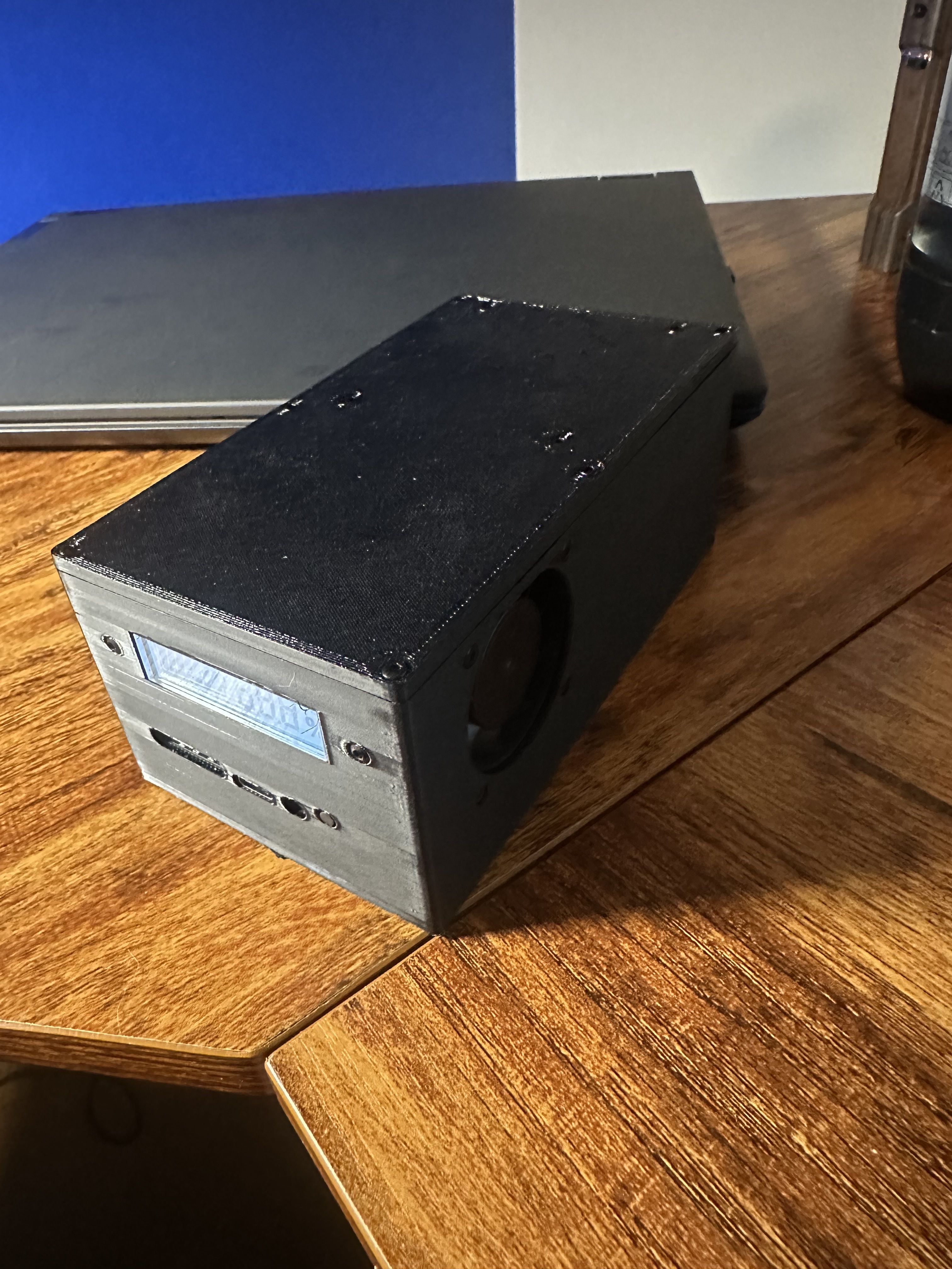
This is a high-capacity portable power bank I designed. The pack is six 21700 cells in series. The outputs are one 140 W USB-C PD port and three 65 W USB-C ports. It was designed to charge multiple devices at the same time, specifically my phone and laptop.
Why I Built It
As a student I use my computer heavily during the day and there is not always a wall outlet available. My battery is good for 3 hours or so before dying, and then I would have to move around to find an outlet. This battery solves that problem, letting me charge wherever I want and tripling my computer’s battery life. I considered buying one, but with the price of retail options it made more sense to learn and build it myself.
Design Decisions
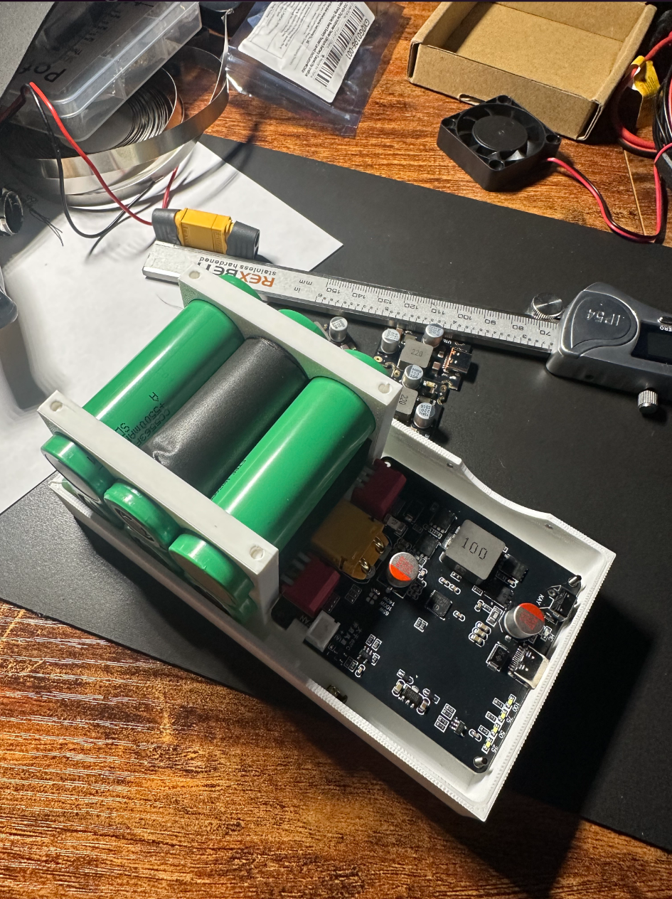
I went with Samsung 58E 21700 cells because of their energy density and cost. Bought at $2.85 per cell, that is cheap for 5,330 mAh cells. While their discharge rating is low, it was still high enough for my purpose. The BMS is a generic 6S board. The main charging and discharging board is an IP2366 rated for 140 W in and out. My computer charges at 100 W through USB-C, so I wanted something with a bit of headroom. The other three boards are generic 65 W USB-C boards that amply serve the purpose of charging anything small via USB-C, and in theory can even charge small laptops.
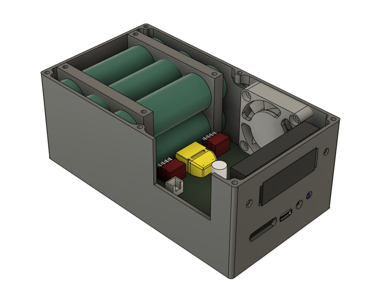
The case is made of straight PETG with M2 bolts and heat inserts. I chose PETG because of its ductility and fracture resistance. I did not want PLA because it would deform under heat too easily, and ABS is too rigid; it would break before bending. PETG has enough ductility to provide vibration damping to the cells and boards.
There are several internal fillets to increase wall thickness in the corners, and the bolts are all recessed to sit flush with the case. The cells are held in their own cell holder part to isolate them from the shell itself and provide more damping.
Build and Packaging
Once everything was modeled and designed in CAD I printed all the parts: the top and bottom of the shell, the cell holders, and the risers for the IP2366 board. The cells went into the cell holder with vibration damping foam added for extra tension, then were spot welded into a 6S pack. All four power delivery boards were soldered to the BMS, and then I soldered the pack to the BMS. The design let me drop the whole assembly into the case, tighten some bolts, and put the lid on.
What It Demonstrates
This project was whole-system work: picking cells for a specific load, integrating a BMS and four power delivery boards, and designing an enclosure that holds all of it together and survives being thrown in a bag. It is the electrical and packaging counterpart to the mechanical projects elsewhere in this portfolio.